Water Lift System
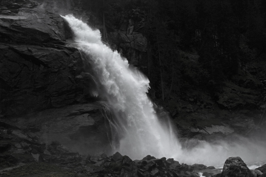
Hydraulic Cycle Described in Scripture
Ecclesiastes 1:7 (NASB)
7 All the rivers flow into the sea, Yet the sea is not full. To the place where the rivers flow, there they flow again.
The above scripture describes how water flows from the highlands in streams and rivers and continues to flow into the ocean. The ocean is heated by the sun causing water vapor which blows inland in the form of clouds. When the clouds are forced into higher altitudes by the inland mountain ranges then the cloud vapor cools and condenses into water droplets. This causes rain and thus the cycle continues causing more water to flow toward the oceans from higher to lower elevations.
In the same we humans are created in the image of God to become creators. People can imitate the natural processes created by God and move water to higher elevations where it can be used to irrigate crops and turn turbines of hydroelectric generators to create energy. This can be done in a continuous cycle just like God’s nature which causes streams and rivers to flow to the ocean on a perpetual basis.
Below are some simple concepts about how water can be lifted to higher elevations and once lifted this same water can moved by gravity flow to lower elevations. This gravity-flow water can produce work and turn turbines to generate energy and irrigate crops. In this manner humans can create a self-sufficient system that can produce food and energy and oxygen and everything needed to sustain human life under any conditions.
Cistern and Vertical Pipe
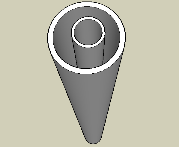
The image above represents a cistern that is 2.4 m (or 8-foot) in diameter. There is a vertical pipe of 508 mm (or 20 inches) in diameter standing within the cistern. The top of the cistern and pipe begin at ground level and project 37.69 meters down below the surface.
Concrete Donut Plunger
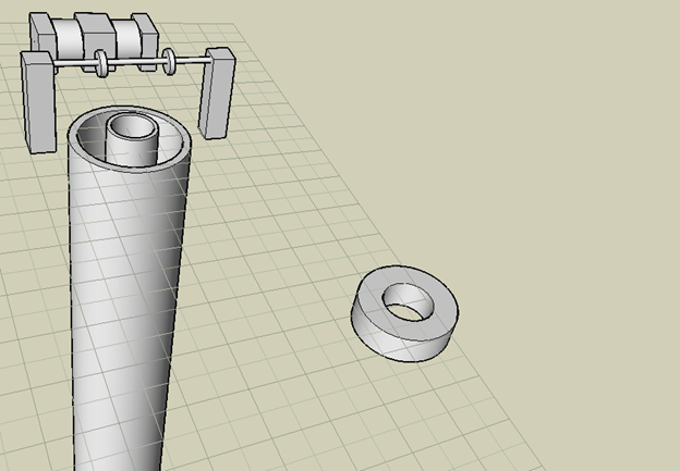
The image above shows a donut shaped object on the right. This represents a concrete donut plunger. This is designed to fit around the 508 mm (20 inch) pipe and provide downward pressure to assist in causing water to flow up the pipe from the bottom of the cistern.
The Belgium Pipe
The Belgium pipe is a name given to an experiment conducted in a deep lake in Belgium. They introduced air into the bottom of a pipe suspended in a deep lake and this caused water flow up the pipe to create an airlift pump.
See the video link “Belgium Pipe” for more details.
There was increased water pressure at greater depths in the lake where the Belgium pipe was tested. When they introduced air into the inside of the bottom of the pipe this caused a low pressure inside. The higher-pressure water from the lake then flowed into the lower pressure causing a flow up the pipe. The rising of air bubbles also assisted in lifting the water to the surface to produce a large geyser. The concrete donut plunder is designed to increase water pressure by using gravity together with the mass of the plunger to replicate the increased water pressure found within a deep body of water.
Hoist and Plunger
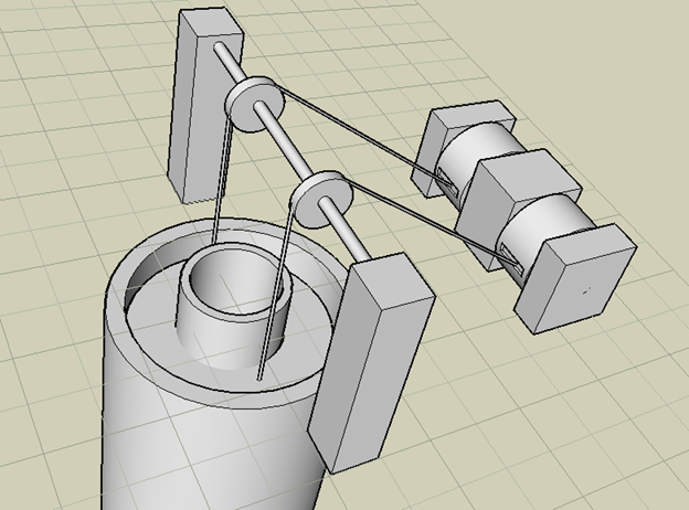
The image above represents the concrete donut plunger as it fits around the 508 mm (20 inch) pipe in the center of the cistern. This concrete donut plunger is connected by two cables to a winch represented by the object on the right in this image. As the plunger is lowered by the cables, it will cause downward pressure on the water in the cistern and aid in causing a water flow up the 508 mm (20 inch) pipe to the surface.
Two Air Lines Attached inside of the 20-inch Pipe (Bottom View)
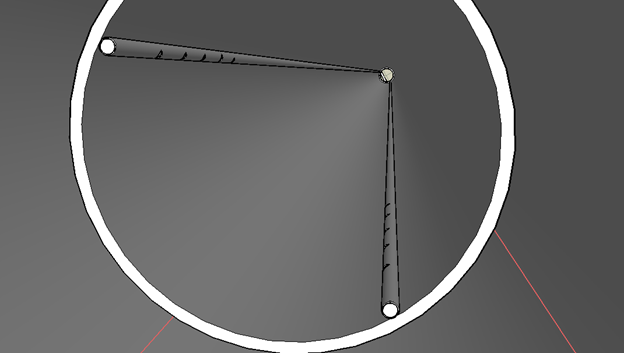
The image above represents two air lines attached to the inside of the 508 mm (20 inch) pipe. The bottom ends of the 19 mm (¾ inch) air lines are capped off to force the air through the holes drilled into the sides of the air-lines. This is a view from the bottom of the pipe where air will be introduced to cause an air/water flow up toward the surface.
Two ¾” Air-Lines Protruding from Top of the Pipe
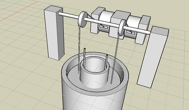
The image above represents two air lines as seen protruding from the top and inside of the center vertical pipe. These are designed to send air pressure to the bottom of the cistern as a “Belgium Pipe” would do.
Air Compressor and Hoses
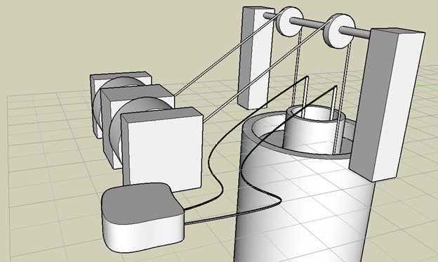
In the image above, the object at the lower left represents an air compressor with hoses leading to the two air-lines attached to the inside of the pipe. These transmit compressed air to the bottom of the 508 mm (20 inch) pipe to create an airlift pump.
Plunger and Air-Lines
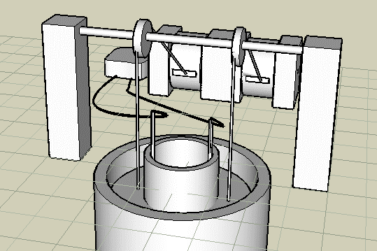
The image above shows both concrete donut plunger (that is lowered by cables and a winch) and also the two 19 mm (¾ inch) air-lines that force pressurized air into the bottom of the 508 mm (20 inch) pipe. If this pipe was submerged into a deep lake, then the outside water pressure would flow into the pipe when air is introduced into the bottom of the pipe. In this situation, the concrete plunger is designed to provide additional water pressure to assist the air-lift pump in bringing great volumes of water to the surface.
Upper Surface Reservoir
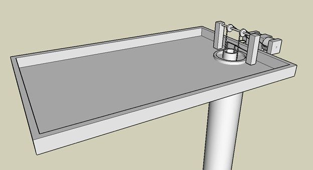
The image above represents an upper water reservoir where the water accumulates before it is recycled again through the hydroelectric generators located on lower levels.
Winch and Air Compressor
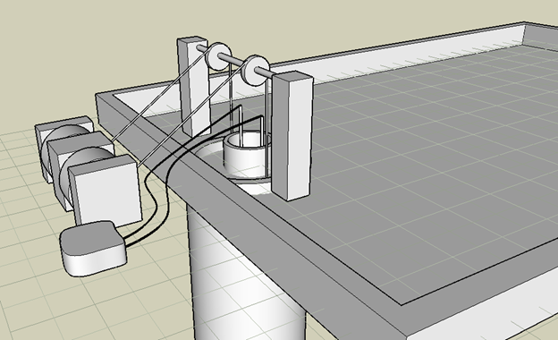
A winch can be designed to operate off hydraulic action which can be used to live the donut plunder counter weight used to provide downward pressure. The winch hoists the weight to the top of the cycle then it is tripped to drop the weight at the top of the cycle and restart the process.
Dual Power Air/Mechanical Water Lift
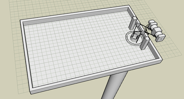
The system can use both air and mechanical lift to force water to a higher level where it can begin the cycle over again in keeping the water powered generators operational without the use of petroleum fuels.
Water Reservoir on Top of FPU
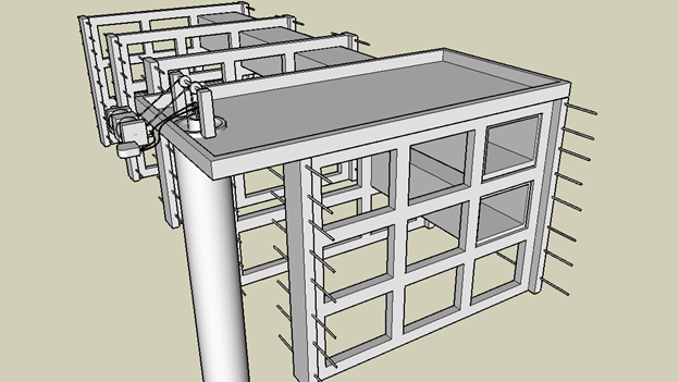
The water reservoir is located on top of the FPU so that once water is lifted to the reservoir then it will operate water powered generators using gravity flow. In locations of extreme cold the system can be placed below the frost line to keep it from freezing.
Water Flows from Top Reservoir to Lowest Level
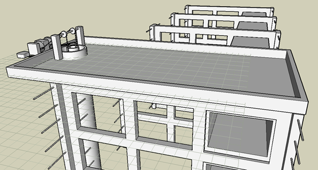
The water from the reservoir will be connected to the plant growth tunnels beneath using PVC pipes to operate the water-powered generators.
Plant Growth Tunnels Below Reservoir
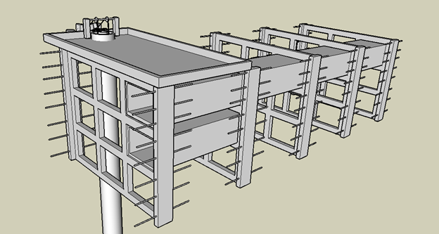
The plant grown tunnels located below the water reservoir will be powered by gravity flow water from above.
Air/Mechanical lift pump
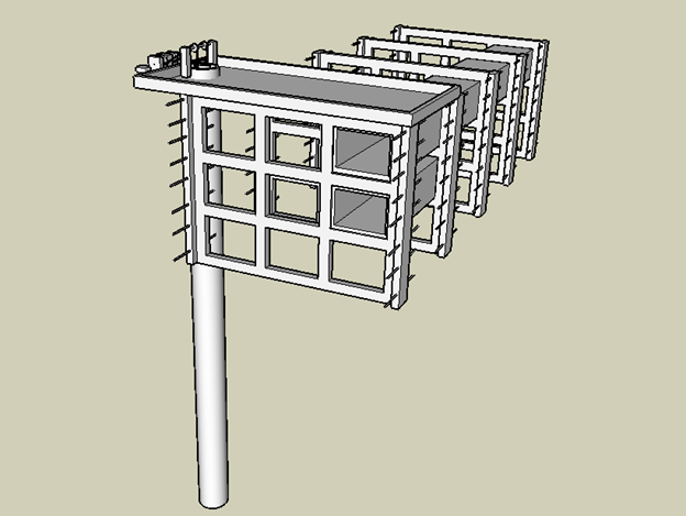
The image above shows that the water is lifted from the bottom of the cistern by dual air/mechanical means and is emitted through the 508 mm (20 inch) pipe into the upper reservoir on the surface. The water then flows from the reservoir to the plant growth tunnels below it by the force of gravity. Every time the water drops to a lower level it will turn hydroelectric generators to produce electric power to run lights for plants growing within the tunnels. The same water also is used to provide aquatic nutrients to the plants.
Water Return Pipe
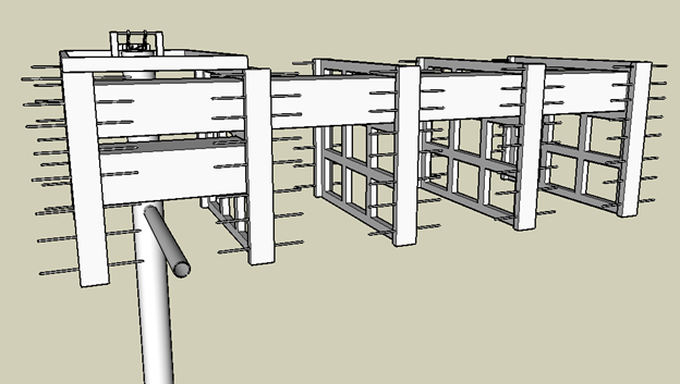
In the image above, a return pipe is shown entering the cistern at a 90-degree angle. This pipe will receive the water after it has flowed through all three levels of plant growth tunnels. There will be a one-way valve where this pipe enters the cistern so that when there is downward water pressure from the concrete plunger, then the valve will close and retain the water inside of the cistern. This valve will open again when the plunder has been lifted to the beginning of its cycle and when the water pressure inside of the cistern has decreased.
With this method we are able to lift water back to the highest level and begin our cycle again. The air/mechanical means of pumping requires no petroleum energy or combustion engines. The air pump and winch can be run using hydraulic motors. We have a system of horse-treadmills that turn hydraulic pumps and these produce oil pressure to run hydraulic motors to run both air compressors and cable winches.
See the link “Horse Treadmill” for more details.
Inline Pipe Turbine
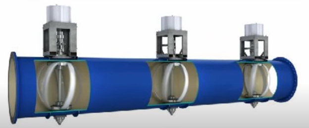
Above is an inline water pipe turbine that can generate electric energy even from the flow of water within mainline water pipes. This is another example of how we can utilize flowing water to generate energy for our living system.
See the link “Inline Pipe Turbine” for more details.