Automated Living System
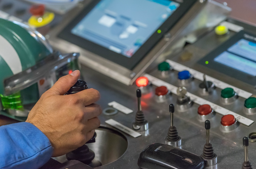
Below are some elementary concepts about how we can build a self-sufficient and automated living system. We did not patient these concepts because all of them have already been used for decades now in some form or another. These ideas can be readily found on Utube so they are nothing new.
Instead, we are only introducing some general concepts here and it will be up to our engineers and innovators who work with us to come up with the working solutions by combining or adapting any or more of these concepts into a working solution.
Family Production Unit
A Family Production Unit (FPU) is a subsurface structure automated structure that is able to produce food, energy, and oxygen for an indefinite period of time. Food is grown in plant growth tunnels using an aquaponics system. In an aquaponics system, aquatic waste from fish or ducks is used to provide plant nutrients to grow plants without the use of soil. Plant roots are suspended in the nutrient water and their roots absorb nitrogen and send the water back clean to the fish tanks. Water for this system also turns hydroelectric generators which provide electric current to run LED plant growth light strips so that plants can be grown underground with artificial lighting. Below are some general concepts about how this system can be built using a subsurface trench-type construction but the same principles can also be applied by using a tunnel system for mountainous regions.
Below are some concepts for building with “trench-type” construction as would be used in areas open-plains regions like those found in Mongolia.
Prestressed Concrete Panel
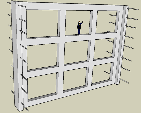
14 x 12 Meter Pre-Stressed Concrete Panel
The image above shows a pre-stressed concrete panel that is load bearing both horizontally and vertically. It can bear loads internally and from above, as well as bearing the load of holding the sidewalls of an excavation in place. It is 14 meters wide and 12 meters high with rectangle shaped ports within that are 4 meters wide and 3 meters high. The framework is 50 cm thick and 50 cm high between the ports. A human figure was placed in the image above for size comparison.
To install this panel, we first cut two parallel trenches that are 16 meters apart and 253 meters long. Then we cut trenches between the two parallel trenches at 90 degrees to the parallel trenches and drop the panel into this trench. The image above shows rods protruding horizontally on both ends of the panels (which represent deformed steel bars). These will hold the panel in place after concrete is poured in the two parallel trenches.
See the link “Cutting Trenches” for more details.
Series of Concrete Panels
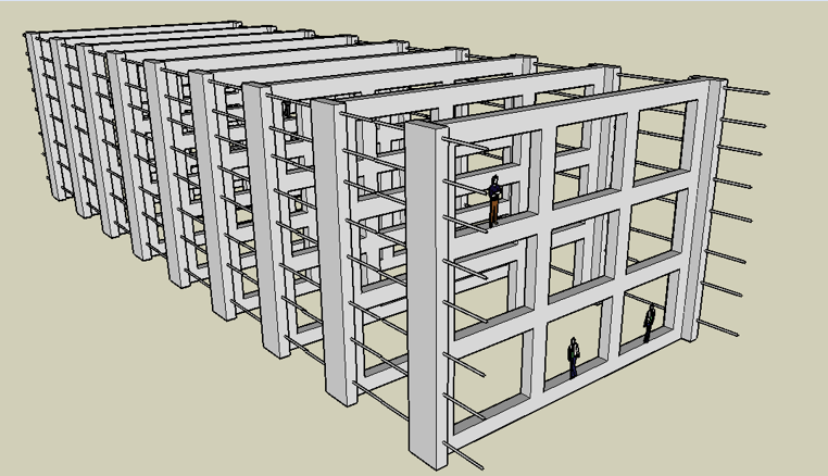
The process of installing multiple panels is repeated by cutting a trench at 90 degrees to the two parallel trenches for each panel installed. When finished, we will have a series of panels standing between the two parallel trenches. When complete we will pour concrete in the two parallel trenches and this will hold the ends of the panels together.
Two Parallel Trenches filled with Concrete
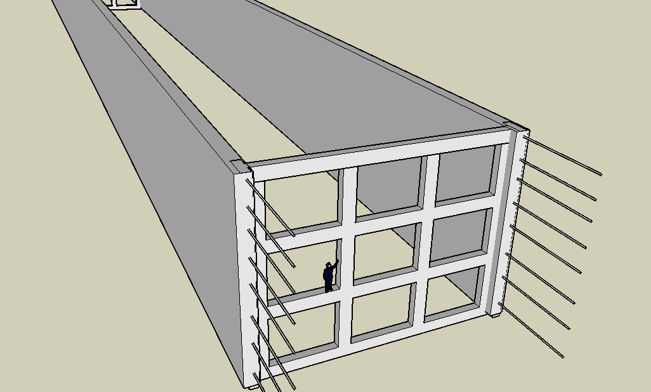
The image above represents the two parallel trenches filled with concrete to create two parallel concrete walls. This image shows one panel installed on one end for illustrations purposes. The concrete is poured around the ends of the panels so that the panels become a part of the two parallel concrete walls. After the concrete walls have been set then the material between the walls is excavated leaving a 16-meter-wide trench where multiple panels will stand.
Two Panels Standing in Poured Concrete Walls
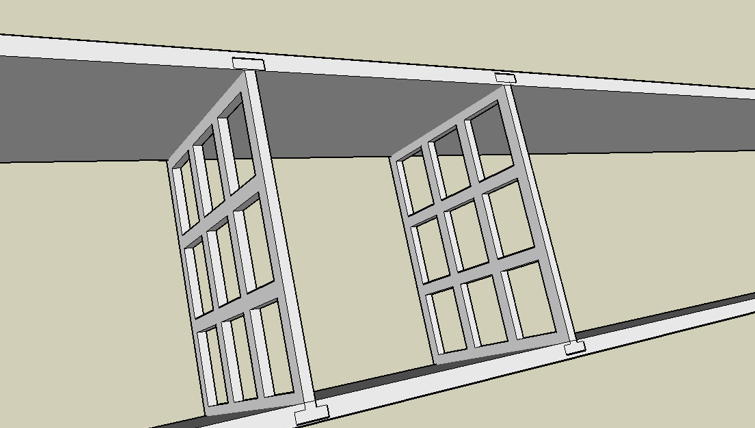
The image above represents two panels from a top view and their ends are supported by the poured concrete walls. The concrete is poured into the two parallel trenches and the soil excavated between the walls leaving the panels standing between the two concrete walls as pictured above.
Standing Panels with Joining Steel Bars
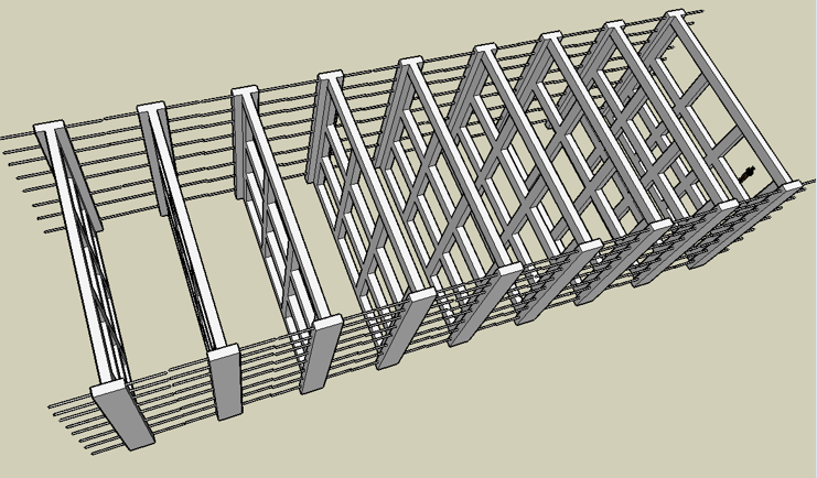
The image above shows a series of standing panels with their deformed steel bars meeting between the panels. The steel bars will become a part of the two retaining walls after the concrete is poured into the two parallel trenches.
Panels with Plant Growth Tunnels
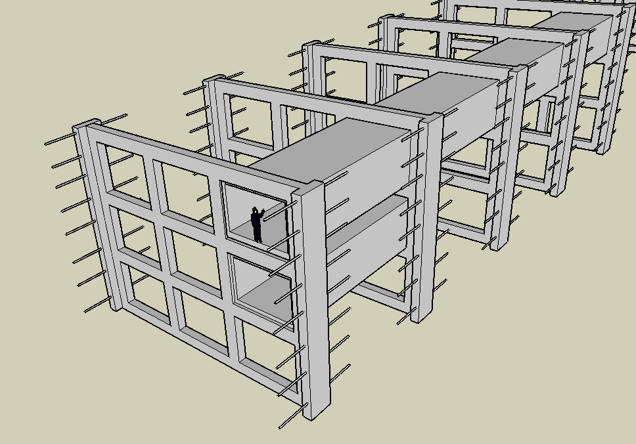
The image above shows how the panels will hold the rectangle shaped plant growth tunnels. The vertical and horizontal load bearing structure of the panels bears the weight of the plant growth tunnels to keep the tunnels on the bottom being crushed if they were stacked one on top of the other. The same panels also provide support to hold the retaining walls in place by resisting the outside pressures of soil weight exerted against the two parallel walls.
Plant Growth Tunnel
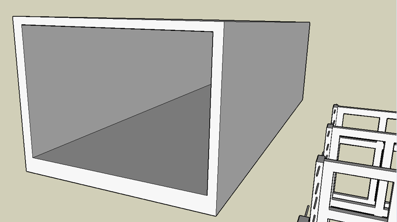
The image above shows one section of a rectangle shaped plant growth tunnel. It is 10 meters long and 4 meters wide and 3 meters tall. The bottom is made heavier than the sidewalls and is reinforced with steel bars much like a bridge beam to bear the weight of being suspended between the panels.
Family Production Unit
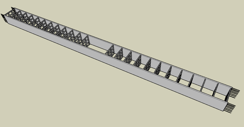
The image above represents a Family Product Unit (FPU) that is 16 meters wide and 253 meters long. This FPU will be placed under a strip of land that is 4,048 square meters or 1-acre in size. There will be supporting panels placed every 10-meters along the entire length and they will support plant growth tunnels that are 10-meters in length. The open space in the center is 30-meters by 16-meters and it will hold three levels. Livestock can be raised on the lower level and the livestock waste will be transferred to a methane gas digester below. The second level can be used for a production work area and the top level can be used as a family living quarters. A single family will have the production capability of this aquaponics system to provide year-round fresh food and vegetables plus a great abundance of fodder for livestock and meat and dairy production.
Double-wide FPU
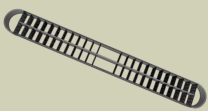
The image above shows how two FPU’s can be placed side by side. The ends are formed with a half-circle concrete wall that enables air to be circulated through both FPU’s. The plants growing in the tunnels will convert carbon dioxide exhaled from humans into oxygen and the people breathe the oxygen created by the plants and algae. Our system imitates the systems found in nature to create a life-support system underground.
This system will be largely automated. I have given a video of an example of an automated fodders system below. This contains some similar concepts of how our system will also be automated even though we do not use sprouted grain fodder for livestock.
See the video link “Automated System” for more details.
The video linked above shows how fodder is produced from grain such as barley which is sprouted in a controlled environment and the sprouted grain can be fed to livestock. Normally it is better to just feed the grain directly to livestock without trying to sprout it first but this video still serves to illustrate how machines can be created to fully automate any type of agricultural production (even that which is used underground).
We have plans to create an automated food production system to grow leafy vegetables and all kinds of food plants using a aquaponic system. This system could even utilize floating water plants like duckweed as a protein source for livestock fodder.
Vegetables are grown in an Aquaponics system as described below:
Aquaponics System
Aquaculture is raising aquatic species like fish in tanks while hydroponics is cultivating plants in water. Aquaponics is a combination of both systems as aquatic waste from fish tanks is used to provide plant nutrients to grow food crops in water without using soil.
The water in this system can also be used to produce electric energy by turning hydroelectric generators. This in turn can energize plant growth light strips providing a light source for growing plants underground.
See the link “Aquaponics Energy” for more details.
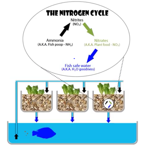
Below is an image of the nitrogen cycle utilized in an aqua-phonics system. Fish waste is used to provide plant nutrients and this fish-water is also used to irrigate and fertilize plants growing in an aqua-phonics system. The plants do not require soil because their roots can be suspended directly in the affluent from the fish. In our system, we want to raise both ducks and fish in the same pond to serve as plant nutrient producers. The ducks and fish also can supply both meat and duck eggs for human consumption. We will also grow aquatic duck-weed in the reservoir which is a protein source for both fish and ducks. The nutrient water is circulated through all of our plant growth trays and after it reaches the bottom level water catch basin then the water is lifted back to the top reservoir by using airlift pumps. Every time the water drops from a higher level to a lower level it also turns hydroelectric generators that power the plant growth lights in this system.
Aqua-phonics System and Nitrogen Cycle
See the video link “Aquaponics 101” for more details.
Algae Panels for Food and Oxygen Production
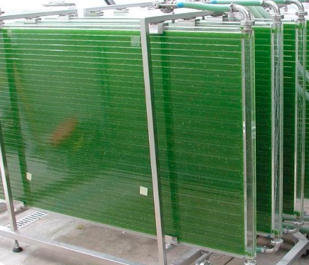
The algae panels pictured above (called a compact plate photobioreactor) are growing spirulina algae which contains complete human nutrition and could enable people to live even if that was the only source of food available to them. This nutritious algae also converts carbon dioxide exhaled by humans or livestock into oxygen making it a perfect “oxygen-producer” for subsurface living systems. Our FPU living system will have all walled surfaces mounted with algae panels similar to these as a source of both food and oxygen.
Recreated Sunlight Underground
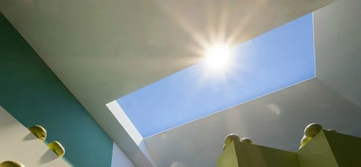
Above is an image of an artificial skylight that actually recreates “real” sunlight underground using the same principles utilized by sunlight passing through the atmosphere around the earth. This technology makes it possible to enjoy sunlight even within a subsurface living system.
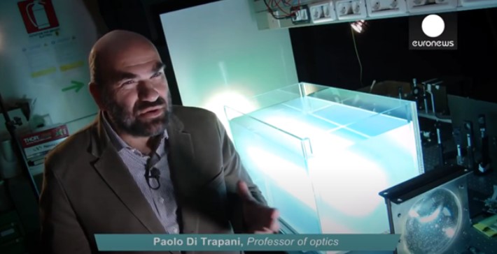
Paolo Di Trapani, Italian professor of optics explains how they can reproduce sunlight by replicating the same system of having rays of the sun pass through the earth’s atmosphere.
See the video link “Recreated Sunlight” for more details.
HD Windows Underground
The video link below shows a HD-video screen that was inserted into a window-frame. Then actual video footage of the outside building “view” was used with some added some “CG-Special Effects” to create a simulated meteor-strike. This video window scene was so “life-like” and “realistic’ that it terrorized those people who had entered the room under the pretext of having a job interview. This is an example of how we can make windows and other aspects of our subsurface living system so “life-like” and “realistic” that it will fool the human senses.
See the video link “HD Windows” for more details.
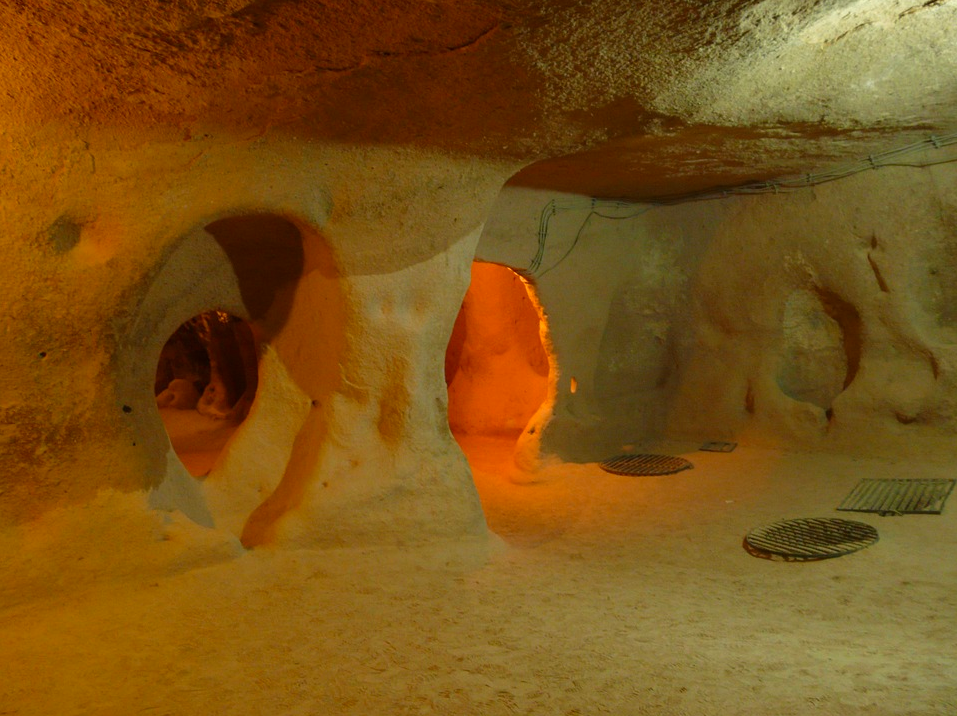
Above is an image of part of an underground city that was created thousands of years ago which was discovered in what is now present-day Turkey. There are been more than 200-underground cities discovered in the area between Kayseri and Nevshir and 40 of these contain three levels or more of subsurface structure complexes.
These underground cities can hold thousands of people and have places for grain storage and storage for olive oil and other food products. There are livestock stables and water-well shafts and ventilation shafts which were all cut out of volcanic rock. All of these subsurface complexes were cut using only hand-tools and manual labor. These structures were so well-hidden that they were not discovered until 1963 when one of the walls was accidently breached revealing miles of tunnels which connected vast areas of chambers and underground living spaces.
See the text link “Derinkuyu Underground City” for more details.
See the video link “Derinkuyu Underground City” for more details.
This is an example of what can be done to create an underground living system. The ancient system in present-day Turkey was created thousands of years ago using hand-tools and manual labor. But we now have the advantage of using modern machinery and advanced technology. Today we can create a system that has real-sunlight and interactive windows and which produces energy and food and oxygen and products needed to sustain human life underground for indefinite periods of time.